
Switches 101
Learn and understand the basics of electromechanical switches and choose the appropriate switch for your application by following along with the below information. NKK’s sales and engineering teams are always happy to help, so please visit the Contact Us page for any further inquiries.
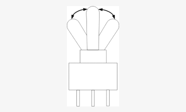
Basic Switch Structure
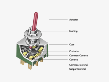
A switch is made up of a variety of components that are essential to get familiar with when designing one into an application. Particularly, the actuator and terminal chosen. A switch operates by Opening (OFF, Break) or Closing (ON, Make) a circuit by changing the contact position.
Pole, Throw, and Position
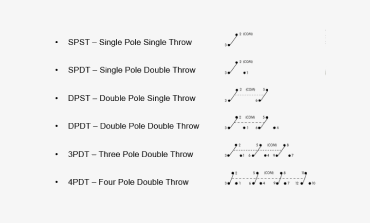
To understand the difference between pole, throw, and position, it is best to use visual examples.
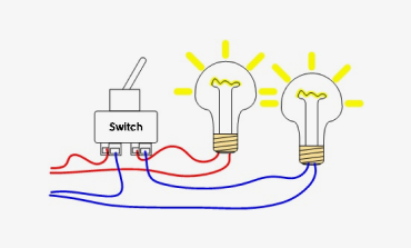
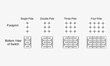
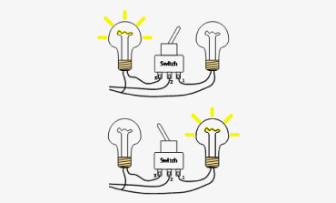
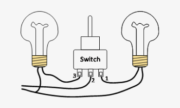
A pole is the number of separate circuits a switch can control at one time. A double pole switch, as illustrated here, is able to control two separate functions at once. A more detailed view of other pole options is below.
A throw, on the other hand, is the number of possible electrical connections within a pole. So, if there is a need for the switch to operate separate connections, a double throw switch would be recommended. This distinction is demonstrated here.
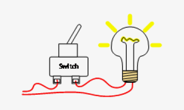
Single Throw (ON-NONE-OFF)
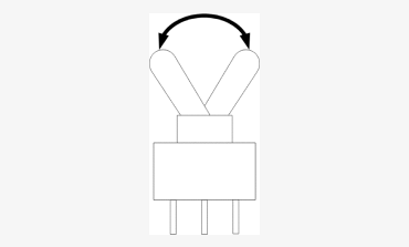
Double Throw Switch (ON-NONE-ON)
In a circuit, a double throw is illustrated by the unconnected dots:
A pole is the number of separate circuits a switch can control at one time. A double pole switch, as illustrated here, is able to control two separate functions at once. A more detailed view of other pole options is below
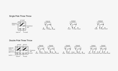
Circuits
Circuits can get confusing when considering the poles and throws needed for a particular application. NKK’s engineers are available to help advise. If an ON-NONE-OFF switch is unavailable, an ON-NONE-ON switch can be used. This is because it can stay unhooked from the extra terminal and have the same function. If a current direction change is needed, a 3-position, double pole, double throw switch does the job. More complicated Special Circuits for ON-ON-ON are demonstrated, giving a wide variety of functions for a single switch.
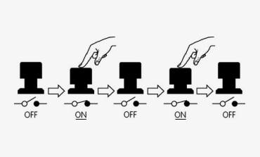
If only momentary action is needed on a switch, the momentary position would be denoted with (). For example, OFF-(ON):
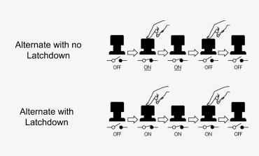
Alternate actuation with or without latchdown are also available. These are also denoted with (), but have permanent states after actuation until actuated again. Alternate actuation looks like this:
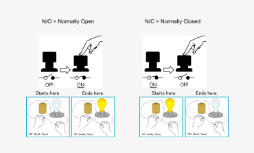
It is similarly important to determine if the circuit is Normally Open (N/O) or Normally Closed (N/C). Which would best suit the design function?
For more information about circuits in illuminated switches, please see the How Illuminated Switches Work training module.
Terminals, Contacts, and Mounting
To decide how best to connect the switch, the following options are available through NKK Switches: solder lug, wire wrap, straight PC, straight PC with bracket, right angle PC, vertical PC, screw lug, quick connect, solder lug with quick connect, SMD, SMD with bracket, and right angle SMD with bracket.

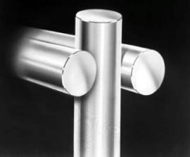
NKK’s Sliding Twin Crossbar (STC) contacts provide the industry’s most reliable contact mechanism. This award-winning contact mechanism offers benefits unavailable in conventional mechanisms: smooth, positive detent actuation, increased contact stability, and unparalleled logic-level reliability. These contacts are available in ultra-miniature and subminiature toggles, rockers, pushbuttons, and slides.
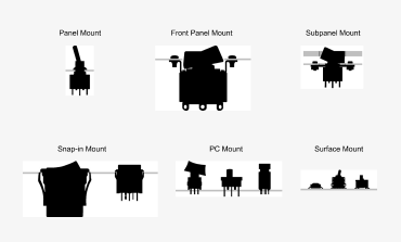
For mounting options, NKK offers panel, front panel, subpanel, snap-in, PC, and surface mount. How they will sit on your module are illustrated here:
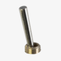
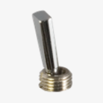
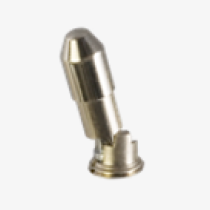
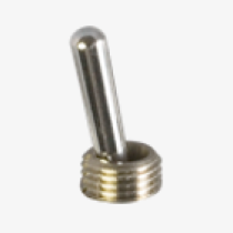
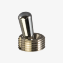
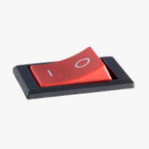
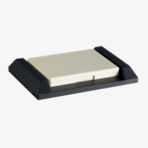
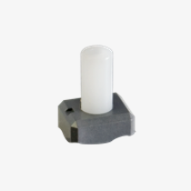
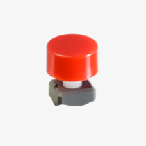
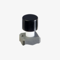
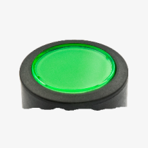
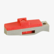
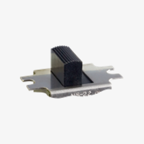
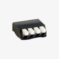
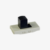
Actuators
Toggles:
Rockers:
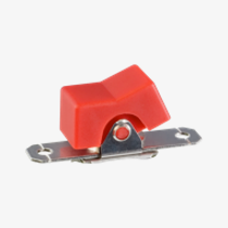
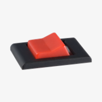
Pushbuttons:
Slides:
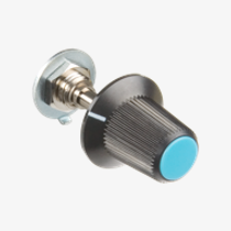
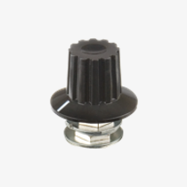
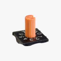
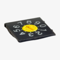
Rotaries:
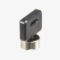
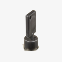
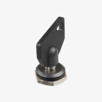
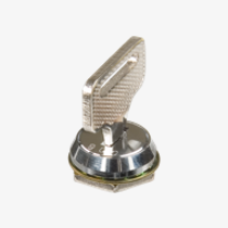
Keylocks:
Switch Ratings and Seals
Many of NKK’s switches are recognized or certified by UL, cULus, CSA and VDE. UL94V-0 ratings are also available on several switch series, and the TV-5, -8 rating is available on the JW rocker series.
IP-Rated devices and splashproof boots help with switch operation in harsh environments. Please visit the IP Rated Switches page to see NKK’s offering. The following are the key ratings for NKK Switches:
- IP60: Dust tight, but not protected against water
- IP64: Dust tight, protected against splashing water
- IP65: Dust tight, protected against low-pressure water jets
- IP67: Dust tight, protected against effects of temporary immersion
When installing boots, please note they should be hand-tight and if there is a locking ring, it goes under the panel.
Now, the difference between Panel Sealed and Process Sealed switches will be important to discuss.
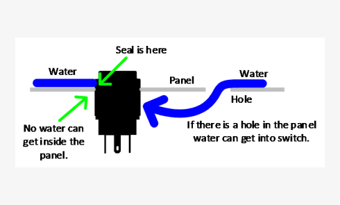
Panel sealed switches seal the panel, it does not seal the switch from water getting in from the back of the panel. An environmental seal is different, it would prevent water from getting into the panel AND the switch. The WT, WR, and WB Series are all environmentally sealed, the YB and S2AW are panel sealed, the M and S Series have dual seal options, and splashproof boots prevent some water damage.
Process sealed switches, however, mean a switch can go through an automated process with solder and washing. This does not mean it can be actuated in the middle of a process; the actuators of process sealed switches should stay in their original factory set position. Please be sure to follow the NKK recommended process when process sealing an NKK switch.
Thank you for taking the time to review this information! Please be sure to take this into consideration when deciding on your switch, and visit the 3D CAD Library to download the CAD of your choice. Please reach out to engineering@nkkswitches.com should you have any further questions.